How to Flash/STLink Ninebot ESX ESC – Fixes Bricked or Updated Controllers (ES1, ES2, ES3, and ES4)
July 1st, 2023
In the case of a bricked ESC/Controller/Control Board, STLinking can save the master control board from needing to be replaced in some instances.
This is often the only way to save a board that has been bricked when the wrong firmware was flashed or an update failed.
This guide shows how to STLink the Controller/Master Controlboard/ESC for the following scooters:
This can happen even without trying to flash CFW or Custom Firmware.
In the case of a bricked ESC/Controller/Control Board, STLinking can save the controller from needing to be replaced in some instances.
Compatible Models
Retail Specific
Rental Specific
What You Will Need
For this process you will need:
- Windows computer
- STLink (Decent quality clones will work)
- Tools to disassemble the scooter and access the ESC
- Dupont male/female jumper cables
Accessing the Debug Pins
Removing the Pole
Remove the 4x Security Torx T25 screws or Hex Screws that hold the handlebar in place on the pole.

The handlebar screws in place.
Remove the 4x Security Torx T30 screws or Hex screws that hold the pole to the base.
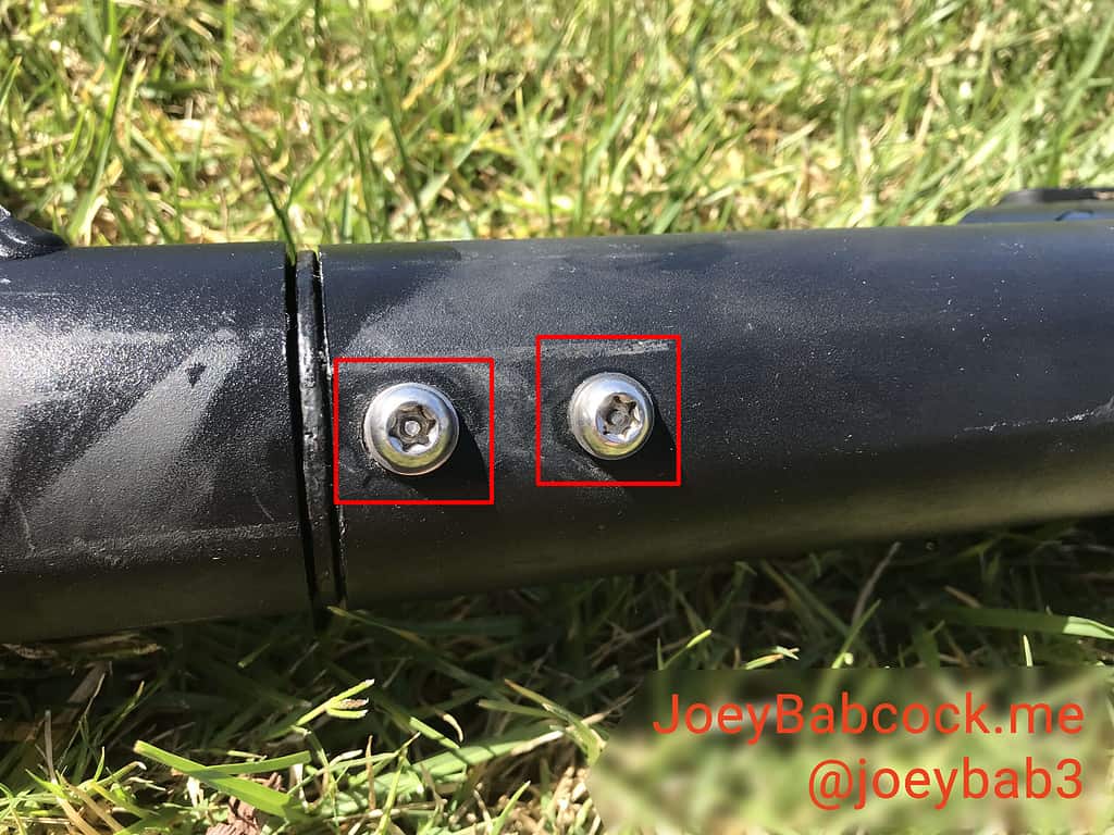
The front pole screws in place.

The rear pole screws in place.
Accessing the ESC
Next, if you have one, remove the external battery.
Two screws hold the battery on the bracket.
These are either security hex or regular hex.

The two screws holding the external battery on the bracket.
This will expose 3 more screws.
Take care removing these screws as they strip very easily.

The 3 easily-strippable screws.
The bracket may be slightly stuck but once these 3 screws are out it can be removed.
If you do not have a bracket then you will have three screws holding the battery in place within the pole.

The 3 screws that hold the internal battery in place within the pole.
You will also have a charging port cover to remove.
Remove the top cover to reveal two screws holding the cover on.

The port cover removed.
Finally, one more screw holds the ESC in place on the pole.

The final screw holding the ESC in place within the pole.
Next comes arguably the most annoying part of the disassembly, removing the waterproofing grommets.
On the top and the bottom is two grommets that are twisted in place.
Press down hard with a large flathead screwdriver and twist counter-clockwise until the slots line up with the metal ridge within the pole.

Keep the grommets attached if you can.

The parts of the grommet.
In some cases, pushing the rubber inner part through the plastic retainer ring will make it easier to remove.
Attempt to keep the wires pushed through the rubber part.
Once both are separated the whole mechanism slides easily out of the pole unless the pole has been damaged or bent.

The battery/ESC internals.
Disassembling the ESC
The internal battery unplugs fairly easily but the BMS connector may need needle-nose pliers to remove the connector.
3 longer hex screws hold the heat sink in place.

2 shorter hex screws hold the charging port in place.

2 shorter hex screws hold the external battery port in place.

Once all screws have been removed, you can pull the ESC to remove it port end first.

The ESC being removed from the housing/heatsink.

The ESC removed from the housing/heatsink.
Download Software
Download STM32 STLink Utility from the ST website.
Scroll down and click “Get Software” and enter your email to receive a download link.
Install it and open it.
Flashing
Connect the STLink to the Master Control Board
Connect pins to 5v/VCC, GND, SWDIO, and SWCLK as shown below.

The pins and where they should be connected.
You can solder to these for a better connection or hold DuPont connectors as shown in the image.

Using dupont cables to connect to the STM32.
Here I did a poor solder job but it still works.
STM32 STLink Utility
Download the 1.3.9 full dump .bin from ScooterHacking.
You can only flash full dump files or the ESC will not function.
Always check that you are downloading files from trusted sources(aka ScooterHacking) to avoid flashing malicious firmware.
Open STM32 STLink Utility and attempt to connect to the esc with the button shown below.

Click the button shown here to attempt to connect.
You should be warned that readout protection is enabled if it is connected successfully.

The warning will be fixed in the next steps.
Next, press CTRL + B to open the chip settings.
Select “Disabled” under “Read out protection”.

The chip settings
The warning will be fixed in the next steps.
Next, click the open icon on the far right as shown.

Click to open the file.
Click to open the file.
Select the esc_fulldump139.bin file you downloaded earlier.
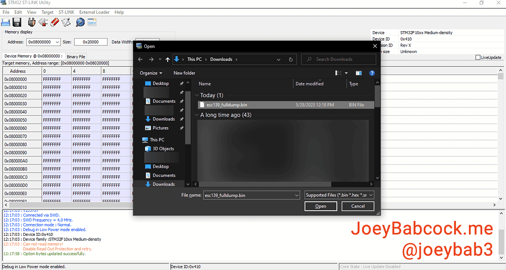
Click to open the esc_fulldump139.bin file you downloaded earlier.
Click to open the esc_fulldump139.bin file you downloaded earlier.
Click Target->Program & Verify or press CTRL + P.

Open the programming menu.
Open the programming menu.
Confirm one last time that the file you are flashing is the full dump and then press “Start”.

Match the settings and confirm the file before pressing start.
Match the settings and confirm the file before pressing start.
The program will now program the chip with the full dump.
Once it finishes check the console to make sure it was successful.

Completely finished and successful programming.
- Filed to:
- Electric Scooters,
- Ninebot,
- STLink
Comments
Hi, I do have a rental ES4, I’ve tried flashing the dashboard it came with it, but it doesnt display anything. Do I need a clone dashboard? I was under the impression that the dashboard it came with will work.
Also, I assume this ESC flash will make it stop flashing the lights red/flickering when moving it?
Thanks.
With rentals there can be quite a variety of things that are non-retail since it was one of the early fleet models.
What brand was the rental in service with previously? That can help to tell what sort of customizations they had on it.
It’s also easier to compare the versions installed with stock versions to see which ones need to be flashed.
A red light flickering as opposed to flashing a pattern likely means it is still locked and on rental firmware which will have to be stlinked to remove.
Thanks for the quick response.
It was on Uber, its an Uber Jump SNSC1.0 with external battery attached, I’ve successfully flashed the dash it has on using this tutorial with st link https://www.scooterhacking.org/forum/viewtopic.php?t=15 , the only thing i might have done wrong is that I soldered back the C15 resistor after.
Well, the back lights flash red every 2-3 seconds and they blink rapidly if i move the scooter, I assume this is from the controller?
So in the end, is this dashboard usable with the proper flash?
Oh I bought like 8 jumps a while back, those are super nice ones, probably the best kept of the rental SNSC 1.0s I came across and had all the features too like underglow lights.
Does your scooter have Bluetooth capability now? If so try connecting with scooterhacking utility to check the versions, you still have to flash the esc but you may not need to stlink it to flash it, Bluetooth or uart may suffice.
Well, thats the issue, the dash is dead, i mean, nothing is displayed on it, the dash power button does nothing.
I can’t find the scooter in Segway app..
Ah yeah the dash might need to be replaced then, you may have shorted something while stlinking.
I don’t think I shorted anything, I’ve flash multiple times successfully. Could this be from the controller firmware? There is 5v on the output for acceleration/brake from the dash, there are also voltage changes when pressing the power button, so the dash is definitely alive, just doesnt display, the scooter doesnt react in any way at the pressing of the power button, even though the voltages change, so that is definitely not from the dash I think.
Gotcha, well if you feel the dash is still fine then next step would be to attempt to flash the controller, either via uart or stlink. If you have another es1-4 or a friends you could test the dash on that would also be immensely helpful
Well, I’ve managed to uart into it, it had DRV 3.2.4 and BMS 3.0.2, I’ve flashed DRV 1.2.0 and 1.2.2 BMS, now the lights no longer blink when moving it by hand, they do still turn on/off every 2-3 seconds just like before.
Now regarding the dash, I haven’t found my old st link, so got new one, with this I do get
** Verify Started **
Error: checksum mismatch – attempting binary compare
diff 0 address 0x10001014. Was 0xff instead of 0x00
diff 1 address 0x10001015. Was 0xff instead of 0xc0
diff 2 address 0x10001016. Was 0xff instead of 0x03
diff 3 address 0x10001017. Was 0xff instead of 0x00
No more differences found.
So I assume the old one didnt display these errors, and thats why it the dash doesnt work.
In Ninebot IAP i get BLE 0.0.0
I’ve also extracted the ESC serial, its N2LUL … considering this, I still need to take the controller apart and st link it with the file here?
Thanks.
Which versions are currently on bms, drv, and ble?