STLink Ninebot Max G30 Gen 2 ESC
In the case of a bricked ESC/Controller/Control Board, STLinking can sometimes save the controller from needing to be replaced.
This method is also capable of downgrading versions like DRV 1.8.7 and DRV 1.8.8.
This page shows how to STLink the 2nd-gen ESC/controller based on the Artery AT32 chip.
For this process, you will need:
- Windows computer
- STLink (Decent quality clones will work)
- Tools to disassemble the scooter and access the parts
- Dupont male/female jumper cables
This process can be dangerous if done incorrectly so take caution when performing these steps and make sure you use a computer you are comfortable possibly destroying.
If you short a battery line you could end up blowing up your STLink, Computer, and more or even causing a fire.
For the Ninebot ESX Series/SNSC 1.0, use the guide at: STLink Ninebot ESX ESC.
Identify Which ESC Generation You Have
Check out the difference between the Ninebot Max ESC Generations and use the steps below depending on which one you have.
There are 3 different board layouts.
A Gen 1 ESC has bullet connectors and a silver metallic housing. Newer units may have writing as shown in this image. 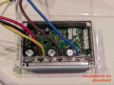
A Gen 1 ESC has bullet connectors and a silver metallic housing. The G30D has 3 capacitors and a different location for the debug pins. 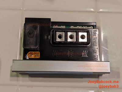
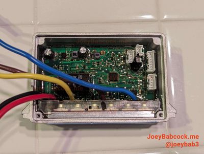
This guide is meant for this model. These versions are based on the AT32 MCU rather than the STM32.
Click the image above to see the guide corresponding to your model.
Accessing the Debug Pins
Accessing the ESC
Start by removing the 18 Security Torx T-15 screws on the bottom.

Using an M4 Allen/Hex wrench or bit, remove the two screws holding the ESC in place.

Carefully unplug each of the connectors.
You may need to scrape more rubber potting compounds away from some connectors to unplug them.
Accessing The Pins
Remove the black shell from the ESC, and take the outer clips off first to slide the shell out from under the upper lip.

Once removed, locate the debug pins.

Connect the pins to the STLink as shown:

Software
Download ScooterHacking ReFlasher from the ScooterHacking website.
Install it and open it.
Flashing
Once installed, open the software and change your model to Ninebot Max.

Make sure you have 'AT32' selected as the chip or you will brick your esc.
To show the console (helpful for debugging errors), press settings -> show console.

Fill out your serial number and current mileage and press 'Launch Recovery'.

Check the console to make sure there are no errors.

Testing
Remove the STLink and plug the ESC back in, then use ScooterHacking Utility to check that your version number is now 1.6.13 or 1.7.3.

From here your motor may not work.
Check Ninebot Max Motor Generations and see if you have a Gen 3 motor.
If so you will want to flash firmware based on 1.8.7 or above (either SHFW or one of the patched 1.8.7 or 1.8.8 versions).