STLink Ninebot Max G30D Gen 1 ESC
In the case of a bricked ESC/Controller/Control Board, STLinking can sometimes save the controller from needing to be replaced.
For this process, you will need:
- Windows computer
- STLink (Decent quality clones will work)
- Tools to disassemble the scooter and access the parts
- Dupont male/female jumper cables
This process can be dangerous if done incorrectly so take caution when performing these steps and make sure you use a computer you are comfortable possibly destroying.
If you short a battery line you could end up blowing up your STLink, Computer, and more or even causing a fire.
For the Ninebot ESX Series/SNSC 1.0, use the guide at: STLink Ninebot ESX ESC.
This guide is for the German G30D Gen 1 ESC with 3 capacitors. It is the board revision v1.5.
Identify Which ESC Generation You Have
Check out the difference between the Ninebot Max ESC Generations and use the steps below depending on which one you have.
There are 3 different board layouts.
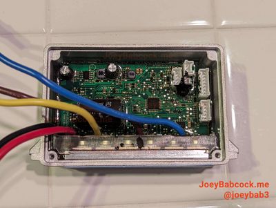
A Gen 1 ESC has bullet connectors and a silver metallic housing. Newer units may have writing as shown in this image. 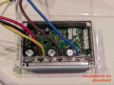
This guide is meant for this model. The G30D has 3 capacitors and a different location for the debug pins. 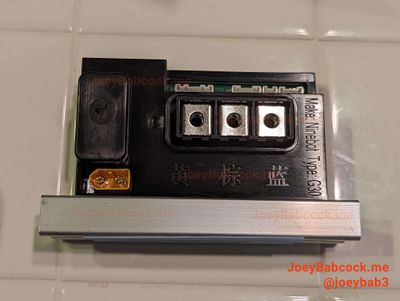
These versions are based on the AT32 MCU rather than the STM32.
Click the image above to see the guide corresponding to your model.
This guide relates to the German G30D Control board, marked AA02 or AB01. Yours may look slightly different or have the 3-pin connector unpopulated.
Gen 1
Accessing the Debug Pins
Accessing the ESC
Start by removing the 18 Security Torx T-15 screws on the bottom.

Using an M4 Allen/Hex wrench or bit, remove the two screws holding the ESC in place.

Carefully unplug each of the connectors.
You may need to scrape more rubber potting compound away from some of the connectors in order to unplug them.
Accessing The Pins
Carefully scrape away the potting compound, making sure not to remove any of the small surface mount components.

Software
Download STM32 STLink Utility from the ST website.
Scroll down and click "Get Software" and enter your email to receive a download link.
Install it and open it.
Flashing
Connect the STLink to the ESC according to the diagram below.
The BMS port red and black wires can also be connected to provide power instead of using the BMS connector and ground point.

NOTE: The pins for SWDIO and SWCLK may be switched on your STLink, if you are having issues connecting try swapping those two pins.
If you are going to attempt to use the BMS connector (and really you should do this anyway) make sure to unplug the battery before unplugging the dashboard and then press the power button a few times to drain the large capacitor onboard.
- Open STM32 ST-Link utility and connect to the ESC using the plug at the top
- Press Target->Connect from the top menu

- Press "Open File" and open esc126_fulldump.bin, you can get it from ScooterHacking.

- From the top menu, press Target->Program & verify or ctrl+p.
Testing
Remove the STLink, and plug back in the ESC. Use ScooterHacking Utility to check that your version number has changed.