How to STLink Ninebot Max/G30D 3-Capacitor ESC – Fixes Bricked or Updated Controllers
October 4th, 2023
Sometimes when updating a Ninebot Max G30/G30E/G30D/G30P/whatever other models Ninebot comes out with, the update may fail.
This can happen even without trying to flash CFW or Custom Firmware.
In the case of a bricked ESC/Controller/Control Board, STLinking can save the controller from needing to be replaced in some instances.
This guide will also be useful if you have updated it to DRV 1.7.0 or DRV 1.6.13 or any future versions where Ninebot restricts the downgrading of the firmware.
This is also the only fix for DRV 1.8.3/1.7.13 or DRV 1.8.7. Anyone promising you a fix over Bluetooth is probably attempting to scam you.
For this process you will need:
- Windows computer
- STLink (Decent quality clones will work)
- Tools to disassemble the scooter and access the ESC
- Dupont male/female jumper cables
This process can be dangerous if done incorrectly so take caution when performing these steps and make sure you use a computer you are comfortable possibly destroying.
If you short a battery line, you could blow up your STLink, Computer, ESC, and more, or even cause a fire.
Identify Which ESC Generation You Have
Check out the difference between the Ninebot Max ESC Generations and use the steps below depending on which one you have.
There are 3 different board layouts.
These versions are based on the AT32 MCU rather than the STM32.
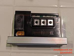
A Gen 1 ESC has bullet connectors and a silver metallic housing. The G30D has 3 capacitors and a different location for the debug pins.
A Gen 1 ESC has bullet connectors and a silver metallic housing. Newer units may have writing as shown in this image.
Click the image above to see the guide corresponding to your model. This one is for the Gen 1 ESC with bullet connectors, but 3 capacitors as well. This generation is used for the G30D regional variant.
Check my wiki article for the different Ninebot Max ESC generations for more info.
Accessing the Debug Pins
Accessing the ESC
Start by removing the 18 Security Torx T-15 screws on the bottom.
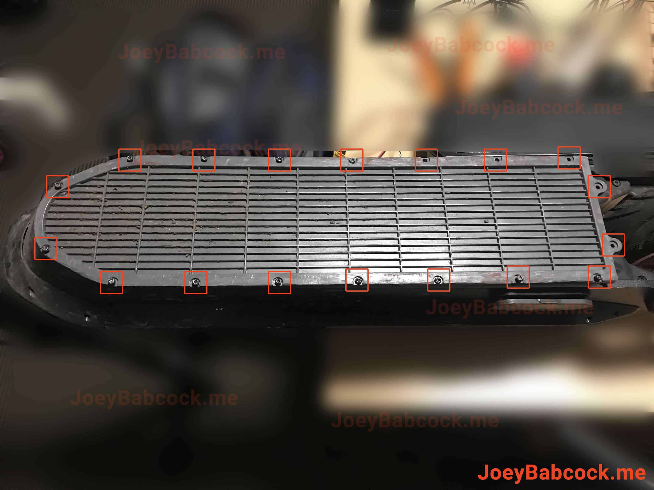
The locations of the 18 screws.
Using an M4 Allen/Hex wrench or bit, remove the two screws holding the ESC in place.
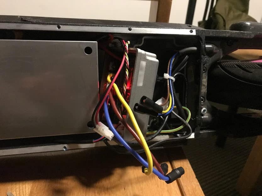
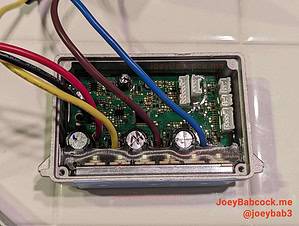
The ESC after being removed.
Carefully unplug each of the connectors.
You may need to scrape more rubber potting compound away from some of the connectors to unplug them.
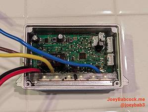
Accessing The Pins
Carefully scrape away the potting compound, ensuring not to remove any small surface mount components.

Be very careful not to damage any of the smaller SMD components.
ScooterHacking Reflasher
A new option recently was published by the team at ScooterHacking for STLinking ESCs.
You can download it here.
STM32 Utility
Download STM32 STLink Utility from the ST website.
Scroll down and click “Get Software” and enter your email to receive a download link.
Install it and open it.
You will also need the full dump file from ScooterHacking.
You can download it directly here: https://files.scooterhacking.org/firmware/max/DRV/esc126_fulldump.bin
A note on downloading firmware: Always ensure you get it from a reputable source.
Always download from ScooterHacking whenever possible, DO NOT TRUST ANYONE TO GIVE YOU FIRMWARE.
I do not host firmware files for this reason.
Flashing
Connect the STLink to the ESC according to the diagram below.
The BMS port red and black wires can also be connected to provide power instead of using the BMS connector and ground point.

The pinout for the STLink for the data pins. Note: SWDIO and SWCLK may be switched, I can’t figure out why but several people have reported this.
Before connecting pins, ensure the battery is unplugged and the onboard capacitor has no energy by shorting the capacitor leads or pressing the dashboard power button a few times while it is plugged in but not connected to the battery.
NOTE: The pins for SWDIO and SWCLK may be switched on your STLink, if you are having issues connecting try swapping those two pins.
Connect your STLink to the pins as shown, you can choose either location for 5v and GND.
- Open the STM32 ST-Link utility and connect to the ESC using the plug at the top
- Press Target->Connect from the top menu
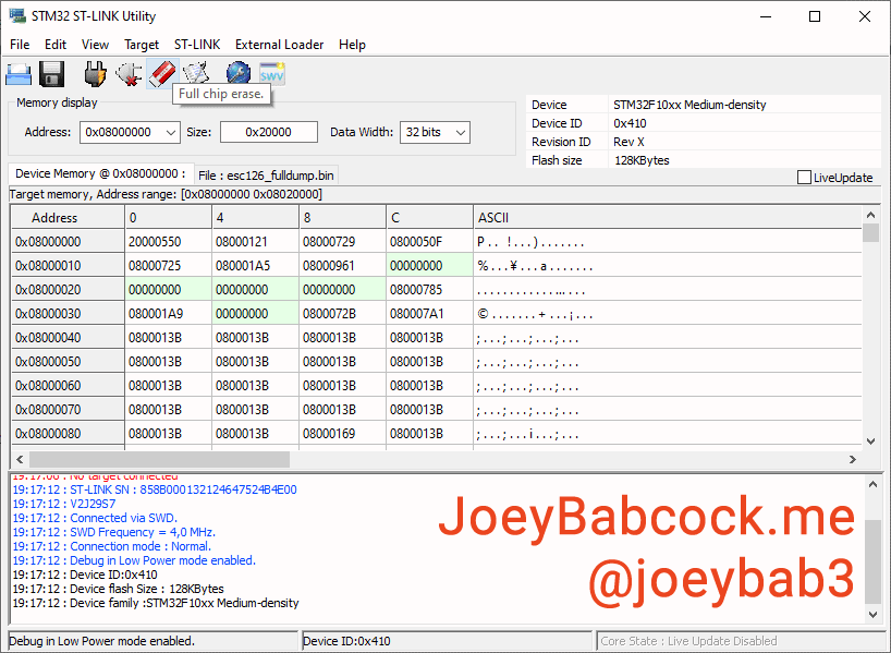
No error messages about “Unable to connect to target” should display.
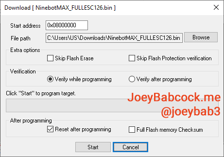
- Press “Open File” and open esc126_fulldump.bin which you downloaded above from “Software”.
At this point, a red LED should light up on the board.
- From the top menu, press Target->Program & verify or ctrl+p.
Once it completes, check the log for error messages.
After that, it should be ready to use again!
- Filed to:
- Electric Scooters,
- Ninebot,
- STLink
Comments
Either the label on my cheapo $10 ST-Link adapter is wrong, or SWDIO and SWDCLK are reversed in the diagram here. If you are pressing the pins into place and it’s just Will. Not. Work, try switching them around.
It’s funny you say that, I actually just switched the diagram around because someone told me the original was switched… I know some STlink clones do mislabel the pins but I am not sure why people are reporting different layouts… very strange but thanks for the heads up
Very informative. Thank you!
Glad it was able to help!