STLink Ninebot Max ESC: Difference between revisions
No edit summary |
|||
| (18 intermediate revisions by the same user not shown) | |||
| Line 1: | Line 1: | ||
In the case of a bricked ESC/Controller/Control Board, STLinking can save the controller from needing to be replaced in some instances. | In the case of a bricked ESC/Controller/Control Board, STLinking can save the controller from needing to be replaced in some instances. | ||
{{ STLink Materials List }} | |||
For the Ninebot ESX Series/[[Ninebot SNSC 1.0|SNSC 1.0]], use the guide at: [[STLink Ninebot ESX ESC]]. | |||
==Identify Which ESC Generation You Have== | |||
Check out the difference between the [[Ninebot Max ESC Generations]] and use the steps below depending on which one you have. | |||
There are 3 different board layouts. | |||
<div><ul> | |||
<li style="display: inline-block;">[[File:NinebotMaxGen1ESC.jpg|link=STLink Ninebot Max Gen 1 ESC|thumb|center|400px|A Gen 1 ESC has bullet connectors and a silver metallic housing. Newer units may have writing as shown in this image.]]</li> | |||
<li style="display: inline-block;">[[File:NinebotMaxGen1G30DESC.jpg|link=STLink Ninebot Max Gen 1 G30D ESC|thumb|center|400px|A Gen 1 ESC has bullet connectors and a silver metallic housing. The G30D has 3 capacitors and a different location for the debug pins.]]</li> | |||
<li style="display: inline-block;">[[File:NinebotMaxGen2ESC.jpg|link=STLink Ninebot Max Gen 2 ESC|thumb|center|400px|A Gen 2 ESC has screw terminals and a black plastic housing. These versions are based on the AT32 MCU rather than the STM32.]]</li> | |||
</ul></div> | |||
Click the image above to go to the guide that corresponds to your model. | |||
[[Category: Scooters]][[Category: Ninebot]][[Category: Max]][[Category: STLink]] | |||
[[ | |||
[[Category: | |||
Latest revision as of 19:53, 17 September 2023
In the case of a bricked ESC/Controller/Control Board, STLinking can save the controller from needing to be replaced in some instances.
For this process, you will need:
- Windows computer
- STLink (Decent quality clones will work)
- Tools to disassemble the scooter and access the parts
- Dupont male/female jumper cables
This process can be dangerous if done incorrectly so take caution when performing these steps and make sure you use a computer you are comfortable possibly destroying.
If you short a battery line you could end up blowing up your STLink, Computer, and more or even causing a fire.
For the Ninebot ESX Series/SNSC 1.0, use the guide at: STLink Ninebot ESX ESC.
Identify Which ESC Generation You Have
Check out the difference between the Ninebot Max ESC Generations and use the steps below depending on which one you have.
There are 3 different board layouts.
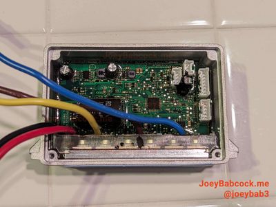
A Gen 1 ESC has bullet connectors and a silver metallic housing. Newer units may have writing as shown in this image. 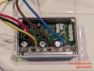
A Gen 1 ESC has bullet connectors and a silver metallic housing. The G30D has 3 capacitors and a different location for the debug pins. 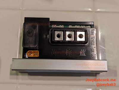
A Gen 2 ESC has screw terminals and a black plastic housing. These versions are based on the AT32 MCU rather than the STM32.
Click the image above to go to the guide that corresponds to your model.