STLink Ninebot Max BMS
In the case of a bricked BMS/battery, STLinking can save the battery from needing to be replaced in some instances.
For this process you will need:
- Windows computer
- STLink (Decent quality clones will work)
- Tools to disassemble the scooter and access the ESC
- Dupont male/female jumper cables
This process can be dangerous if done incorrectly so take caution when performing these steps and make sure you use a computer you are comfortable possibly destroying.
If you short a battery line you could end up blowing up your STLink, Computer, and more or even causing a fire.
This process can also be used to remove downgraded-protected rental/iot firmware if you are returning your fleet vehicle to on-demand use rather than a rental.
Accessing the Debug Pins
Accessing the Battery
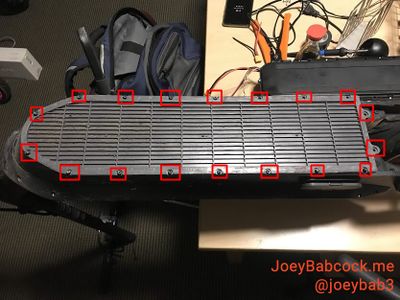
Start by removing the 18 Security Torx T-15 screws on the bottom.
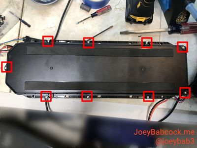
Using an M4 Allen/Hex wrench or bit, remove the ten screws holding the battery in place.
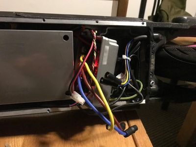
Carefully unplug each of the connectors.
You may need to scrape more rubber potting compound away from some of the connectors in order to unplug them.
Battery Disassembly
9 Phillips head screws hold the top cover in place.
These are EXTREMELY easy to strip so take care.
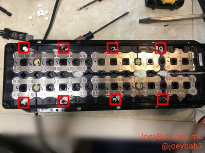
Under the white rubbery spots on the battery, there are 8 more aluminum Phillips head screws.
STLink BMS/Battery
Finding the Debug points
The top of the battery is covered in gray silicon. The area around the debug pins must be removed to access the pins as shown below.
It is just below the BMS 4-pin JST data cable.
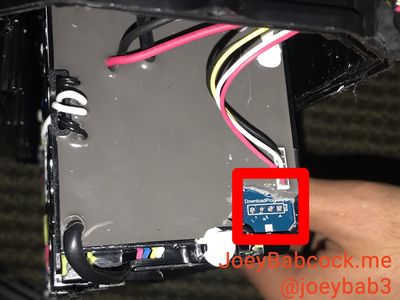
Some boards have a slightly different layout.
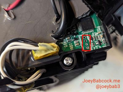
Once you have these pins exposed, either solder jumper cables on or hold them for the next step according to the diagram below:
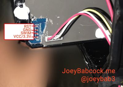
Some boards have a slightly different layout.
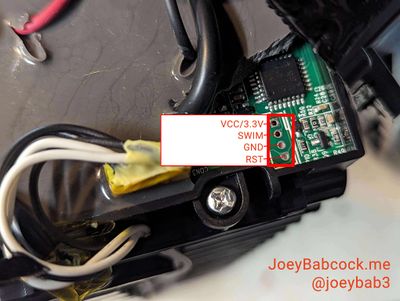
Flashing Stock BMS Firmware
The debug pins must be connected to the STLink as shown. This can be done by manually holding jumpers to the debug points or by soldering wires to connect to the jumpers.
Download the hex file from ScooterHacking, and open it in STVP.
To flash, a separate software must be used instead of the normal openOCD/STM32 STLink Utility method.
To flash it, different software is needed, in this case, STVP.
1. Connect ST-Link to BMS through STVP
2. STM8L15xK6 for the chip
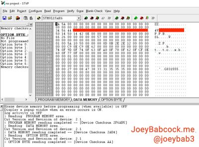
3. In the top menu select Read -> All Tabs
4. Select the bottom tab labeled "PROGRAM MEMORY"
5. Open the full dump file, you can find the full dump file here: Ninebot Max BMS 1.3.4.
6. In the top menu select Program -> All Tabs
Verify Successful Flash
Connect the White of the battery data line to TX and yellow to RX and black to ground in order to check the version. It should read 1.3.4 or 5.3.4, and not 4.4.8 or anything else.
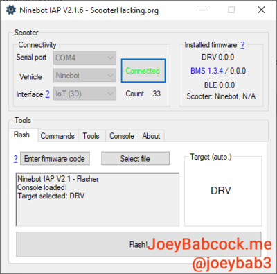
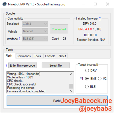
Alternatively, connect the battery to a scooter or skeleton setup and check the version there.